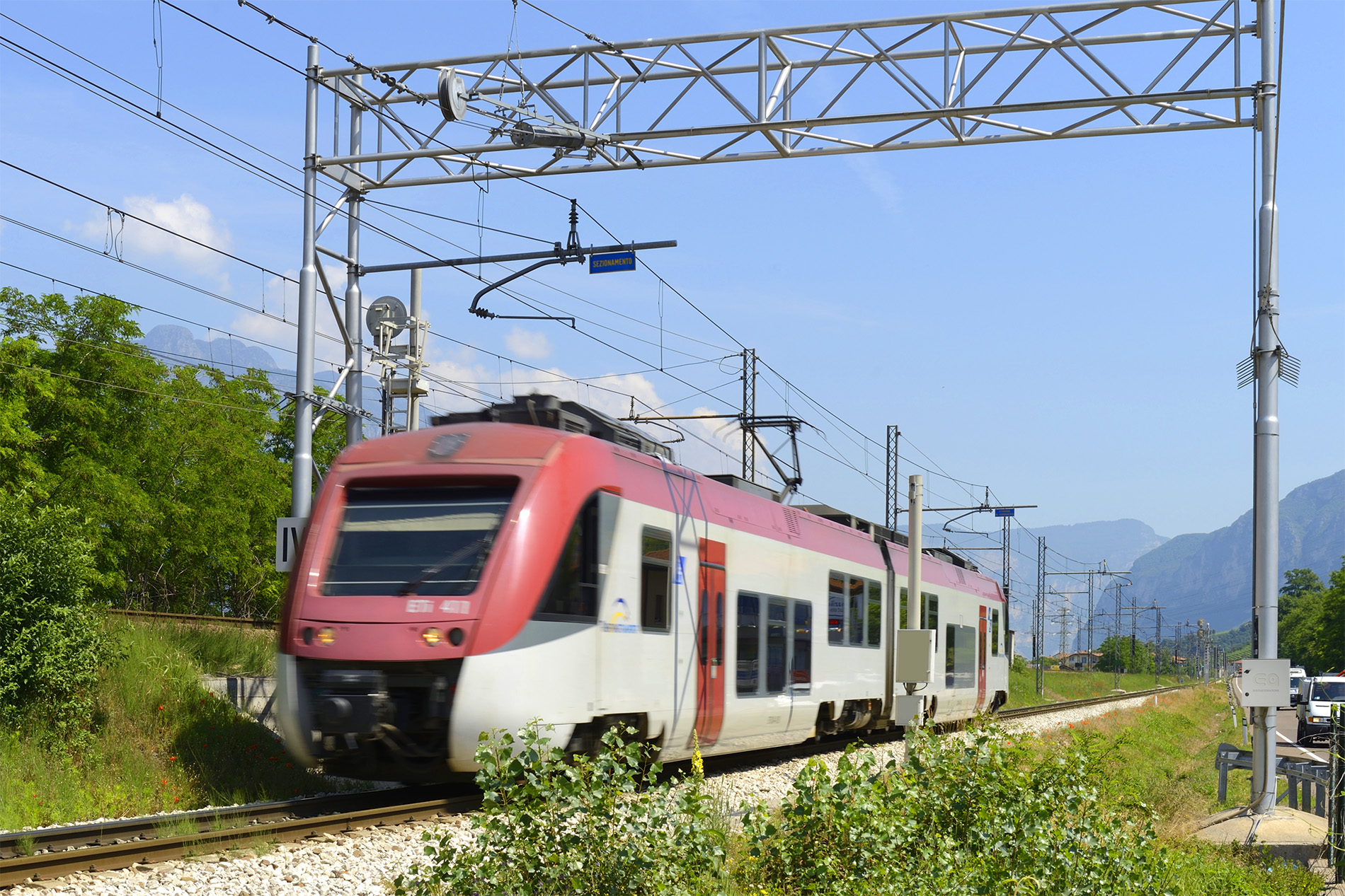
RAILWAY LINE MONITORING
The Cora system, dedicated to the monitoring of railway, tramway and trolleybus power lines, is placed in the automatic regulation points and implements continuous monitoring of the contact line as regards tension, position and ambient temperature parameters. It guarantees maximum control and security.
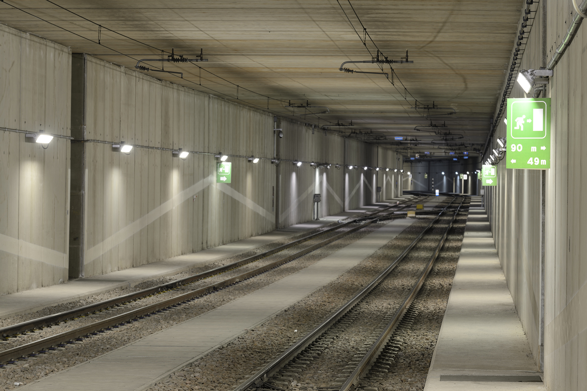
CONTINUOUS CONTROL ON THE WHOLE LINE
The system reads the measurement data and fault or anomaly signals and sends them to a remote control centre, activating the appropriate safety actions, in a very short time, maximum 200 ms. It removes the voltage from the concerned section, following the recognition by the peripheral units of a breaking event of the supporting rope, breaking of contact wires or anomalies of the nominal pulling or elongation values, static and dynamic shortening of the same line.

SYSTEM ARCHITECTURE
The hardware structure of the CORA system can be schematized by four sub-assemblies:
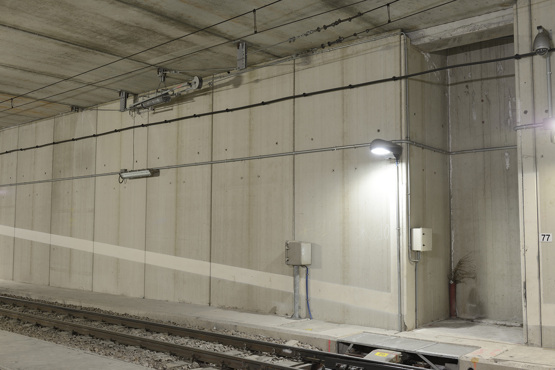
• the TNX peripheral unit located adjacent to the
automatic adjustment station (RA), complete
of the tension sensors (load cell) and protection
(encoder), and of the temperature probe;
• the multimode fiber optic cable transmission line which connects the TNX units and the UPX front-end unit in series;
• the Front-End UPX unit for managing the TNX units,
post in the area involved in the monitoring;
• the control center.
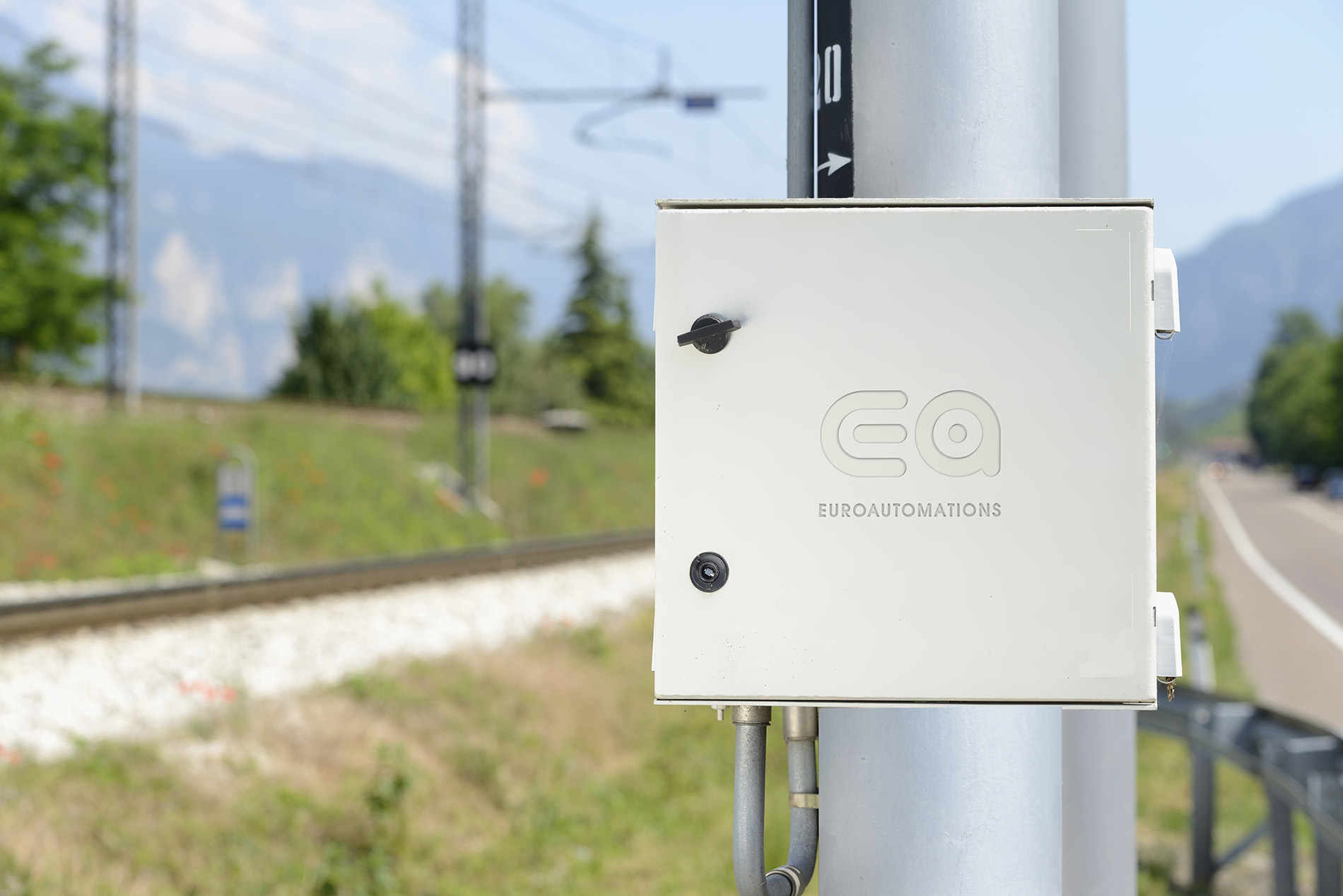
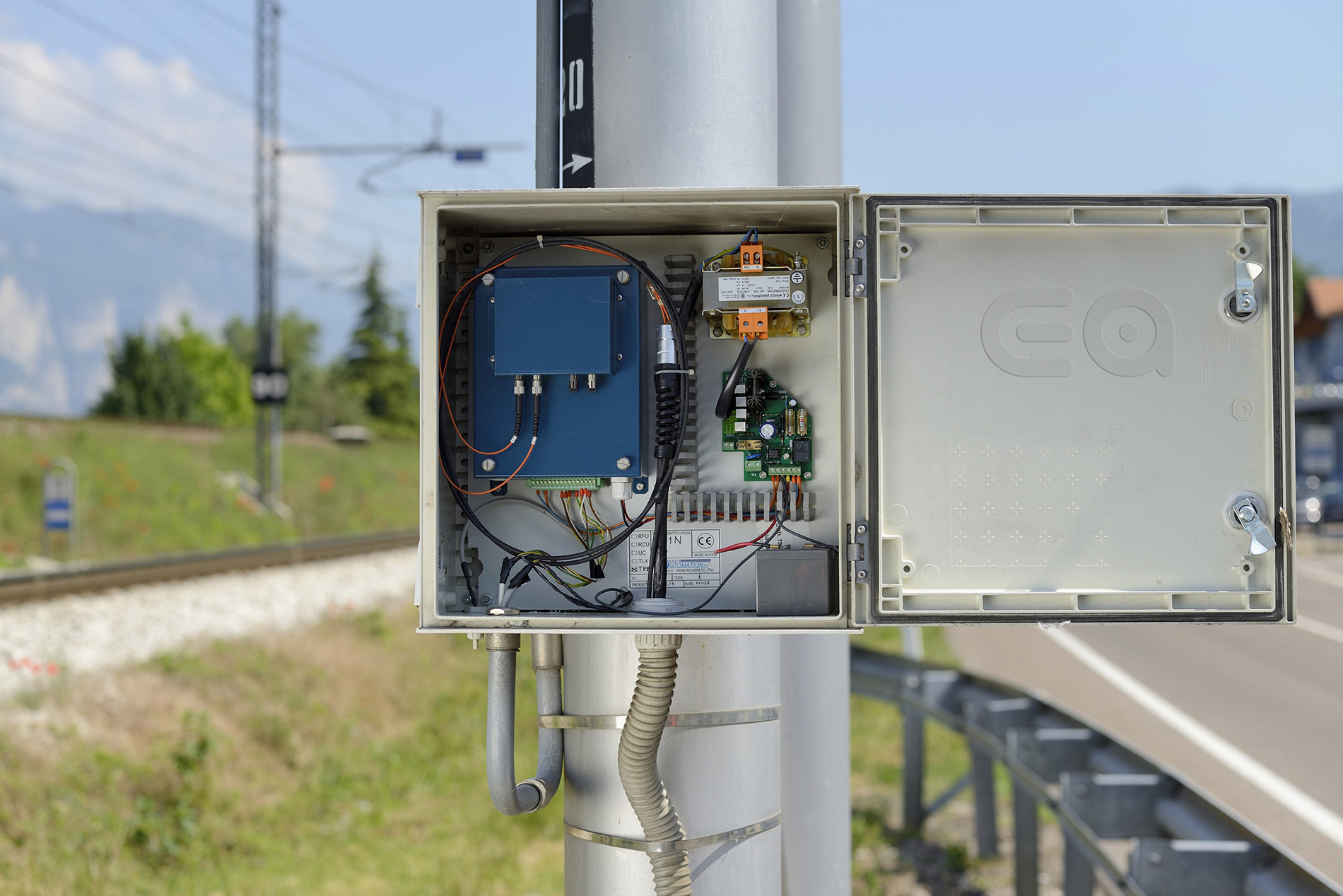
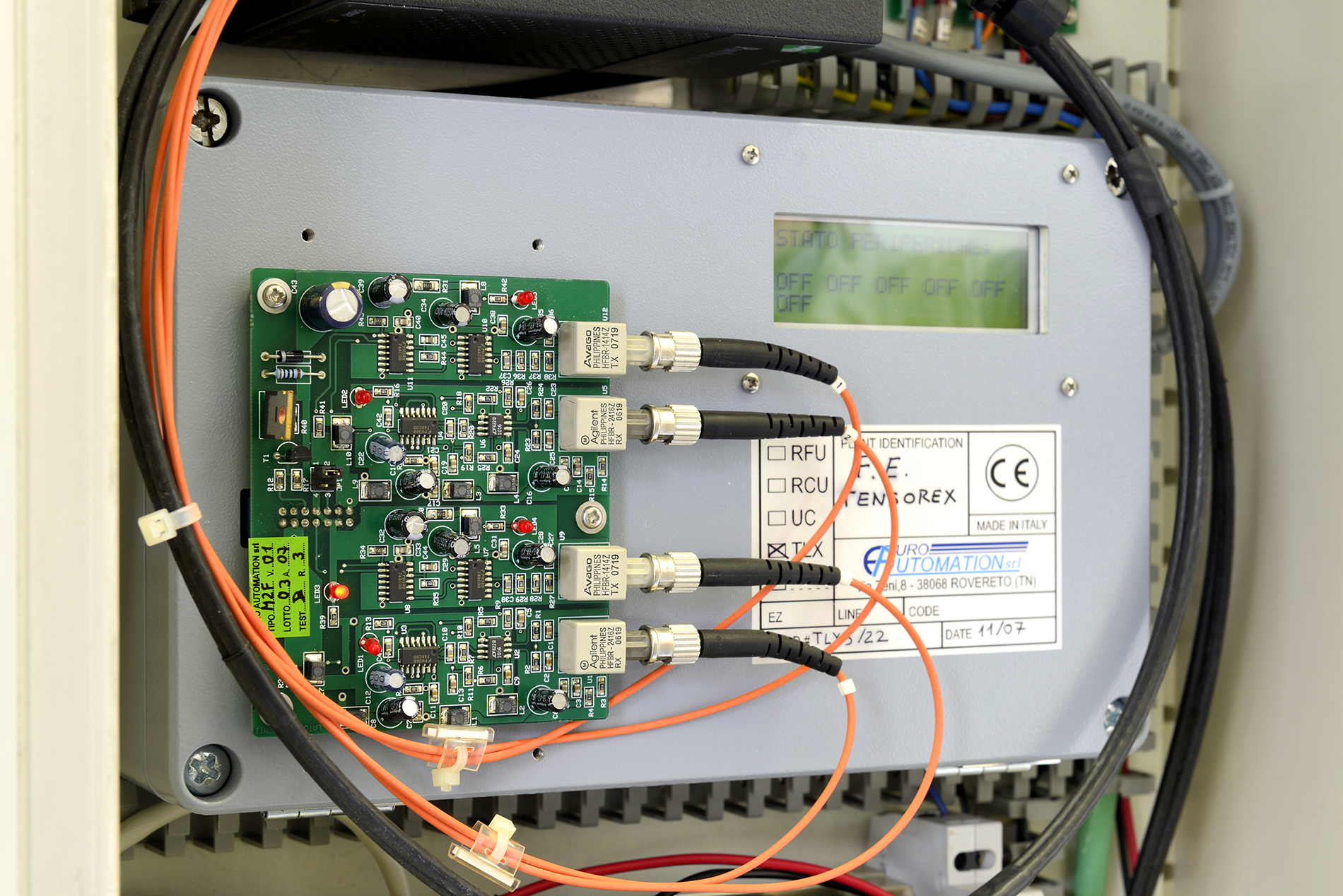
HARDWARE
It consists of a 400x400x200 mm fiberglass-polyester cabinet, mounted on a portal (pole) equipped as an RA post, structured for the acquisition of two tension measurements from the load cell, two position measurements from encoders and an environmental temperature measurement coming from a resistive probe.
The device is powered by a primary source
and is equipped with a power supply complete with buffer battery, capable of ensuring a minimum period of operation of 24 hours in the absence of voltage.
SOFTWARE
The software part is structured for:
1) Identify and avoid the alarm event to the unit
front-end UPX expertise.
The alarm signal, which can be set, identifies the fault/anomaly conditions with:
• shooting out of range allowed;
• elongation outside the allowed range;
• lengthening (shortening) speed higher than the maximum allowed;
2) Automatically process and send the related data to the relevant UPX Front-End unit
detailed event: pull, stretch and stretch measurements
temperature of the relevant section;
3) Receive the set-up of the pulling and lengthening parameters of the relevant section..
